Hobby CNC electronics
I recently started building an IndyMill CNC router. In this post, I’ll share some progress and decisions I’ve made when working on the electronics cabinet of this build.
Please note that everything written below is written in the context of hobbyist CNC router hardware.
A brief intro to hobby CNC routers
A CNC router (or mill) is not a complex machine. Its main job is to move a spindle (~ drill) along the X, Y and Z axis at a specific speed. In a hobby router, you generally use stepper motors, just like you would in a 3D printer - albeit perhaps more powerful ones.
These stepper motors require a lot of power, so they are controlled by drivers. A driver is a device that gets low voltage input signals and translates it into high voltage power signals for the stepper motors.
The drivers themselves are controllerd by a controller. The controller is the heart and brains of the CNC mill: It translates a “job” into signals that it sends to the drivers.
A CNC “job” is defined by “gcode” file. This contains all the commands for the machine to execute. A basic command could be something like “move the spindle 2mm along the X axis”.
There are few more bits and pieces that I’m not talking about here, but these are the main things a hobbyist CNC router is about.
Choosing a cabinet
The first hard part is to find a cabinet that fits your needs. Here were some of my considerations:
- Large enough (to work comfortably and to have space for upgrades)
- Affordable (cabinets often cost hundreds of euros)
- Easy to work with (drilling holes)
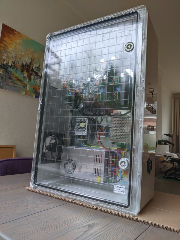
I settled on a cabinet from the German company BoxExpert. I chose the 600 x 400 x 200 mm size. It comes with a transparent door that allows me to see the status LEDs of the hardware inside, and it comes with a metal plate to mount hardware on. I paid about 82 EUR including shipping, so that was reasonable.
Mounting options
Initially, the plan was to mount the hardware directly to the plate. This has one major issue: you can’t change the layout at a later time. Imagine having to start drilling holes into it while there’s already hardware mounting!
DIN-rails were the answer to this! Not only did they help with strengthen the steel mounting plate, they allow me to change the entire setup freely at any time. There are lots of helpful DIN-compatible components out there that helped me in making my build clean.
Cabinet Layout
To make the cabinet layout, I used InkScape. A vector graphics editor like that (or Affinity Designer and many others) is ideal for me: I created a 600 x 400 pixel image, where each pixel represents a millimeter. The end result looks like this:
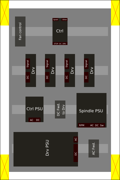
The yellow marked areas are space in the box that is unusable.
Some considerations included:
- Separating high power components from lower power components
- Separating AC from DC components
- Ensuring everything is grounded
Cabinet Airflow
Although airflow isn’t super critical, it’s important to have at least some. We’re not generating a lot of heat inside the cabinet, but since it’s a water-proof cabinet, we want to create some airflow.
I wanted to have a rough idea of how different kinds of airflow would behave, so I used the free tier of SimScale to model some scenarios. Simulating airflow for the cabinet is overkill for a project like this, but it was fun to experiment with.
The first design has an intake fan on the bottom of the cabinet and an exit hole on the top-left. The downside of this designis that we can’t put the cabinet on a flat surface without obstructing the airflow:

The second design has an intake fan on the bottom-left and the outtake hole on the top-left:

The last design is the one I ended up chosing, but both were viable options.
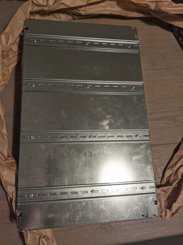
Mounting the DIN rails
The first real build step was mounting the DIN rails on the steel plate of the cabinet. I used a medium-strength thread lock for the nuts and bolts. I also ensured that the plate could be grounded by drilling an extra hole for grounding.
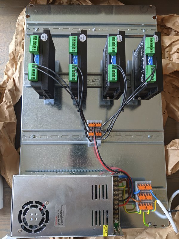
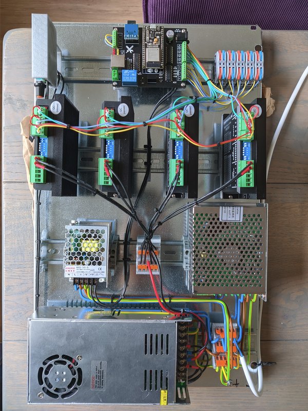
Mounting the first components
Once the rails were ready, it was time to try out the first components: The top row has all 4 stepper drivers, connected to the power supply below. I’m using Wago clamps to tie it all together. The power cord is temporary:
DIN mounting options
There are a lot of DIN parts on Thingiverse. A lot of the DIN brackets that I used come from there. Some of them were custom. The controller and fan brackets are a remix of an existing ones on Thingiverse:
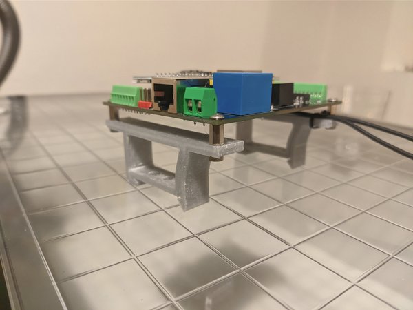
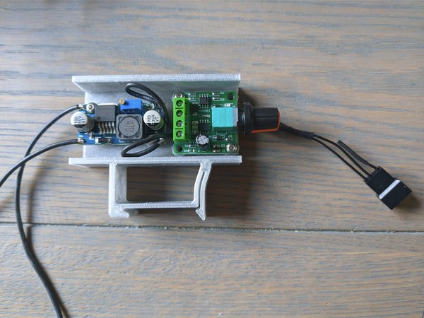
Finish mounting the components
The CNC controller that I’m using as Grbl32bits board from Makerfr. I’ve mounted it together with its power supply and the fan controller in the below picture:
Finishing the cabinet
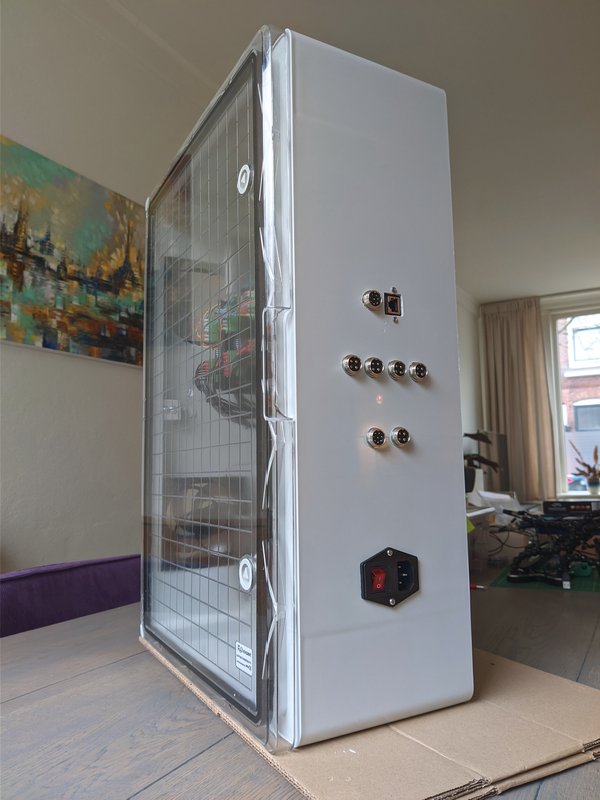
The next step was drilling holes in the cabinet to facilitate all the connectors:
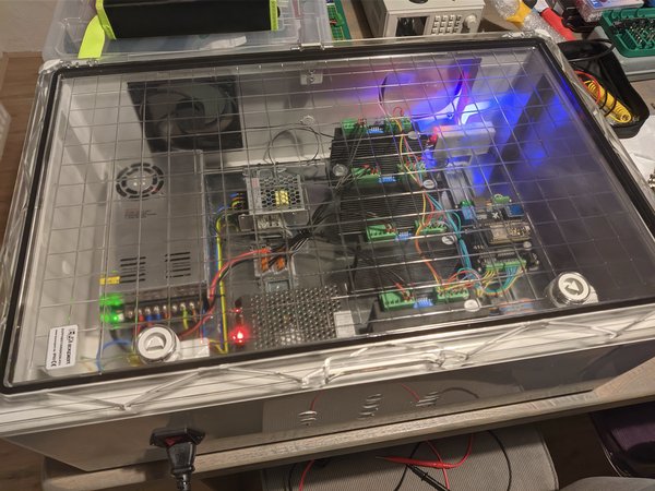
In case you are wondering: yes, that is indeed my living room table being used as a workbench. My wife is awesome for putting up with it.
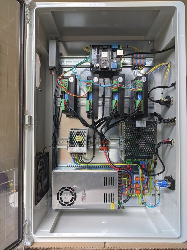
After everything is wired up, the cabinet is finished!
You can find my collection of 3D printable parts here.