OpenPyrojet Print Head Prototype
A few weeks ago, I joined the OpenPyrojet project. OpenPyrojet intends to build 3D printer technology based on thermal spraying. In this post, I’ll show you how I assembled the print head prototype.
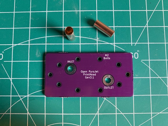
This is what the finished print head looks like:
How does the printer work?
The feedstock of the printer is a mix of micrometer-sized particles (e.g. metals or ceramics) with a fuel source like IPA or naphtha. A monofilament wire is inside the fuel chamber. Heating the wire creates a hot gas, which is then pushed out of a nozzle, mixes with air and catches fire. Due to the heat, the metal melts and hits a surface (substrate) to which it attaches.
Let’s begin!
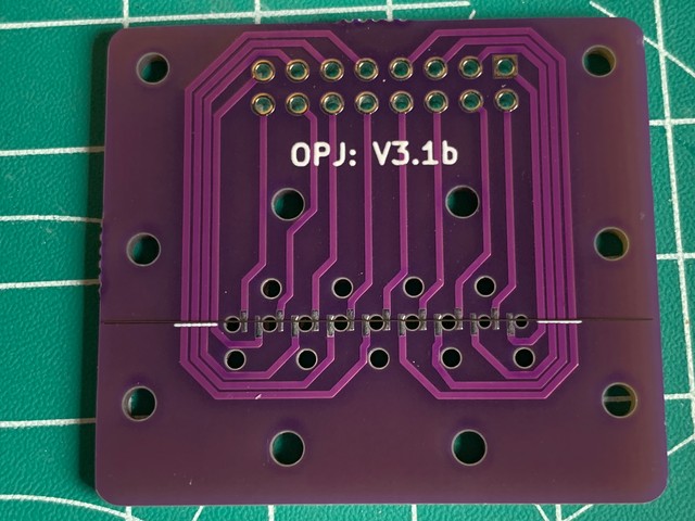
To build a strong print head, we’re using multiple layers made from PCBs. These layers are stacked in the order as they are laid out below:
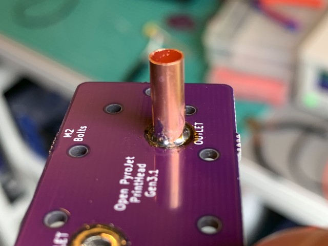
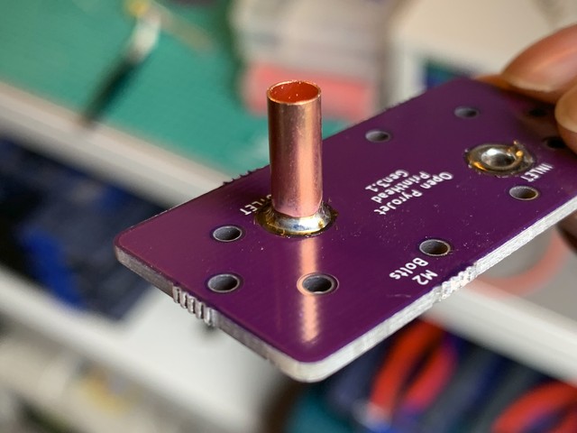
I first prepared the inlet and outlet. I need to connect Viton tubing to the
print head, so I’m soldering small copper pipes (3 mm diameter) to the PCB.
The picture shows a larger copper pipe, because I used the wrong size when taking pictures:
I started with adding solder to the pads:
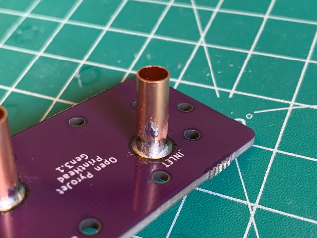
Initially, the solder will likely not connect neatly all around the copper pipe. It might look like the picture below. I take some extra solder on my iron and then place the iron at the base of the copper pipe to fix this issue:
Another problem that might occur is when your solder smudges. I cleaned it off by wiping my (cleaned) soldering iron on it. It’s not problematic if there is some solder on the side, but I have to make sure it’s not sharp. That way, it won’t cut the Viton tubing later on:
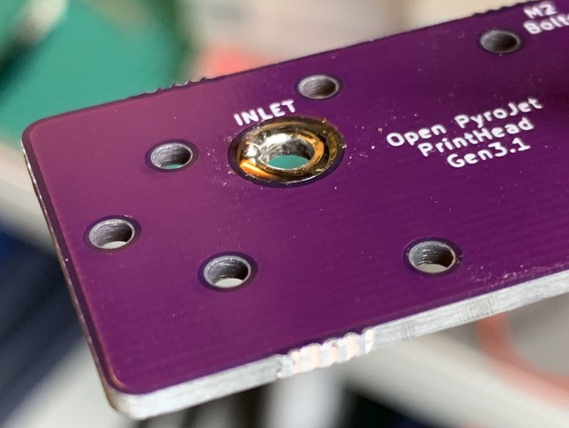
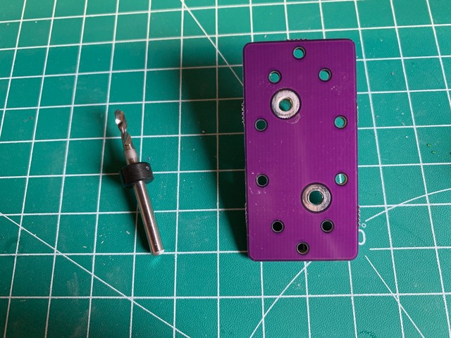
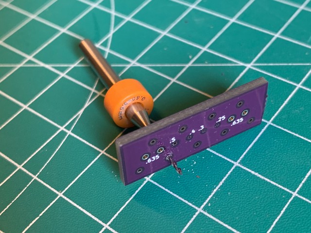
When I used too much solder, the inlet became too narrow. I could’ve desoldered
it. Instead, I used a set of drills to carefully drill it out by hand.
I kept increasing the drill diameter by 0.1 mm until the diameter was the right size:
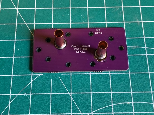
Finally, I had a neat collar on the copper pipe:
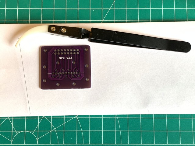
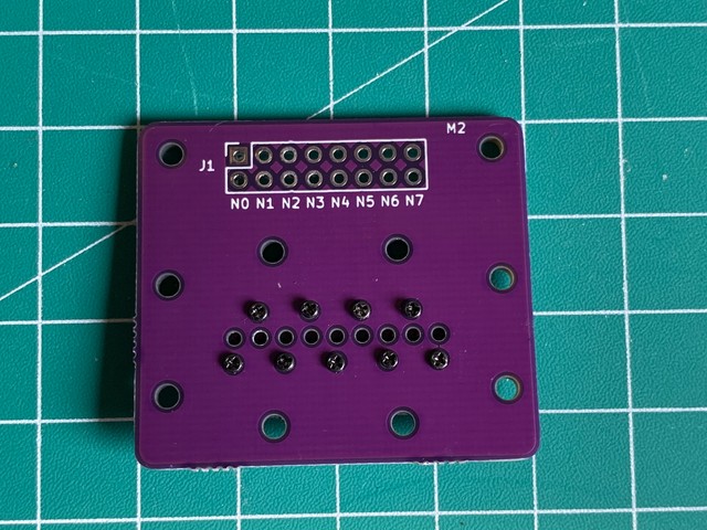
The next step was to put the monofilament on one of the PCB layers. This monofilament is what heats up the fuel, which causes the fuel to eject through the nozzle. The filament gets sandwiched between the nozzle PCB and the PCB that holds the connector. I store the filament in a folded sheet of paper:
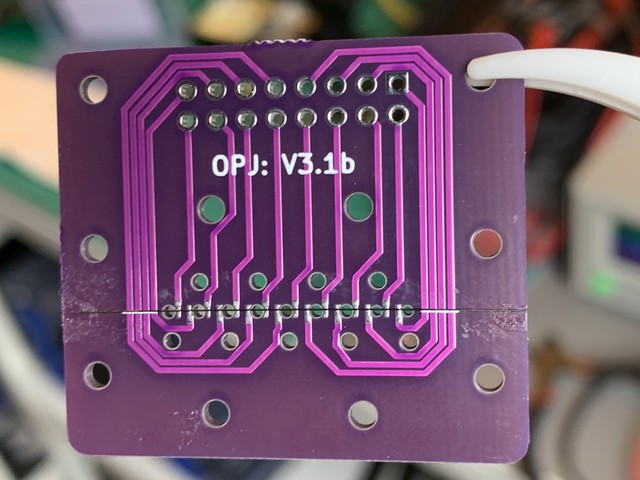
First I cut the filament to size. We make it as wide as possible, so the thickness of the glue won’t interfere with the electrical conductivity:
Combining them is tricky, because the filament won’t lay still on a flat surface. I used some CA glue on the edges to keep it into place. I learned later that glue is not the ideal way. In the future, I will tape it near the edges if the PCB with some kapton tape.
The nozzle PCB layer had holes that were too small in diameter. I widened them
by hand with some cheap drills, slowly increasing the diameter 0.1 mm at a time:
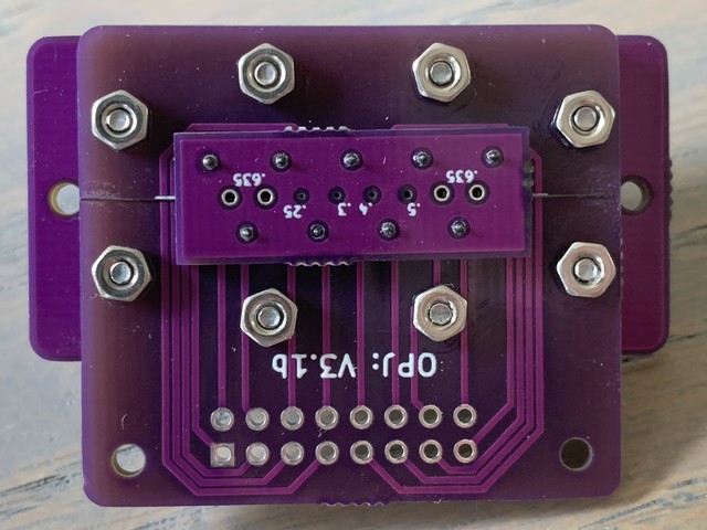
When attaching the nozzle PCB to the connector PCB, I start with a single row of screws:
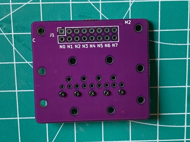
It’s important to tighten the screws evenly, so initially all screws are kept loose. I then tightened them carefully and as evenly as possible. When everything stops sliding around, I start measuring resistance before continueing to tighten further. The resistance measurements are repeated until the values are in an acceptable range.
I had to make sure that the nozzle plate wasn’t crooked, like in the picture below:
The prepared PCBs are ready to be combined. I took 8 pieces of M2 x 10mm and
some M2 nuts to match. I also used medium-strength loctite:
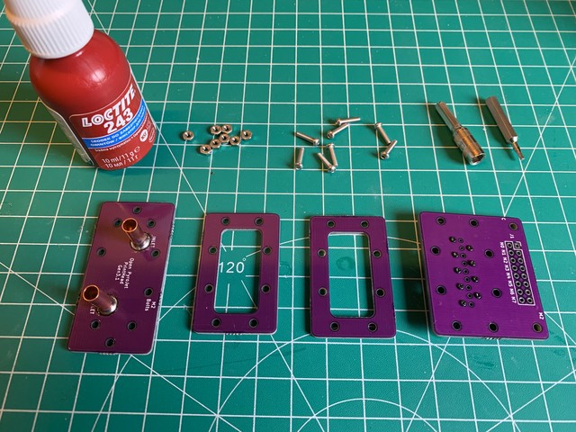
At this point, I have a finished physical assembly: