Building a handheld PC
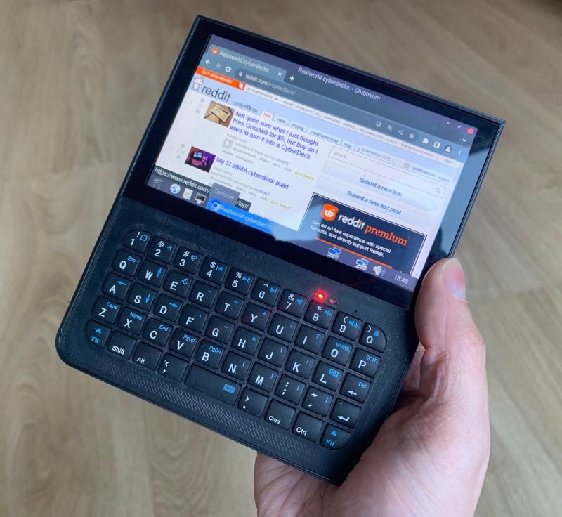
I’d like to share with you my latest project: Decktility!
For several years, I’ve been looking for a project where I could dump a bunch of creativity in. A project of my own, that would be challenging and rewarding. Preferrably a project that combines electronics and software. Handheld PCs always had a special place in my heart. Palm III was my first one, and a bit later I got my hands on a Sharp HC-4500. I was intrigued by the Yarh.io projects and early this year I considered buying a uConsole. The uConsole was supposed to be shipped in March, but currently it’s still pending. So with a bunch of ideas and motivation, I started my own handheld PC project: Decktility.
Initial design criteria
I wanted to challenge myself and push the boundaries of homebrew solutions. The Yarh.io Micro 2’s design was too crude for my taste. It was clearly limited by the hardware availability at the time of development. The Yarh.io documentation gave me a good understanding of what I was about to embark on. I set out to make device that looked more refined. I wanted the end result to be sufficiently light, and the battery life had to be at least a couple of hours.
At this point, I was already considering the BigTreeTech Pad 5 as a foundation, as this was the thinnest touchscreen and Pi combination that I could find. It seemed logical that I wasn’t going to make a foldable device. Making a foldable device would pose several problems:
- The Pad 5 would introduce about
15 mmthickness on one side, while the side with the keyboard would be at least about20 mmthick considering an18 mm18650 battery cell and a case.35 mmwould not be acceptable. I considered a regular flat lipo, but I didn’t like that they get spicy when they short-circuit. - Hinges are difficult to implement well. The screen part would be heavy, and you don’t want it to open/close while typing.
So the decision was made: it was going to be a package size similar to Yarh.io Mini 2 and uConsole.
Prototyping
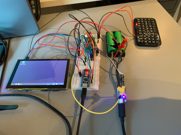
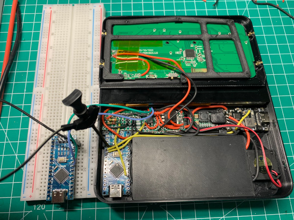
Before starting the 3D design, I bought some basic components online. This allowed me to measure them, so I could get an idea of how much space each component would take up. It also enabled me to start building up a prototype:
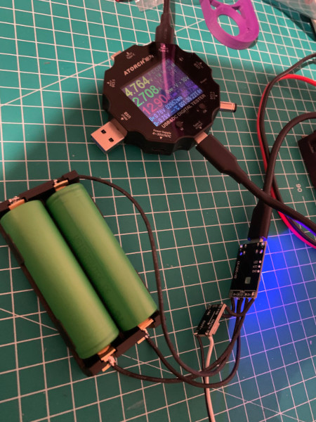
Just like the wiring in the assembly guide, I started by building up the power delivery:
A USB battery management system (BMS) that can charge two 18650 lithium cells, paired with a
5 V step down converter as the Pi, keyboard and fan would require 5 V.
I used a USB-C PD tester to verify the power while charging.
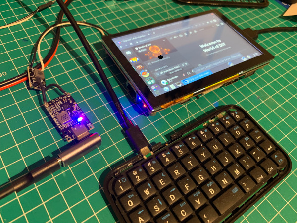
Once that was working, I added some breadboard wires and connected the Pi:
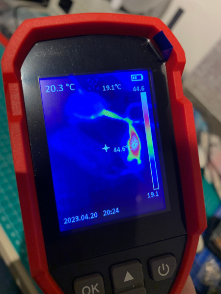
I found out that that the BMS was getting quite hot while charging. It was stepping up the 5 V from USB
to about 8.4 V that the batteries require. Increasing the voltage is much less efficient than decreasing it,
so there is more heat involved. This implied that I would need to accomodate cooling for this scenario.
45 C is not too bad in open air, but it wouldn’t be great in an enclosure, where the Pi would generate heat too.
In theory, having a battery, a switch and a Pi is going to result in a working product,
but what if the battery was running low? If the power switch would remain on, it would drain and damage the battery.
To solve this problem, I introduced an Arduino Nano. The Arduino would end up doing many things, but it started
with reading the voltage from the battery. To do this, I added two resistors with a high resistance value,
because they would always be connected to the battery and thus leak power. By selecting 2.2M R and 3.9 MR,
they would leak only 0.82 μA (5 / (2200000 + 3900000)). That’s about 4.1 μW, or in other words: it would take
203252 days to drain a 20 Wh battery. It’s not going to be problematic this way.
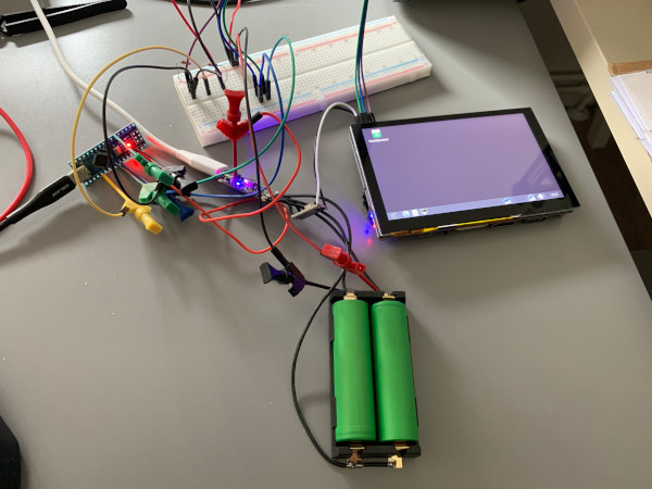
Now that we know when it’s safe to turn on the hardware, I had to add the ability to actually do so. I used a special kind of transistor - a power MOSFET (or “power FET”). The green PCB behind the cable mess holds the FET circuit:
Around this time, I started designing the CAD prototypes in OnShape. Many hours were spent measuring and drawing various components that would go into Decktility. I needed their 3D representation so I could do an integration test of sorts as I was creating the case:
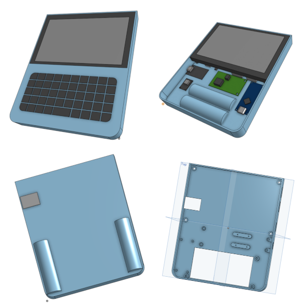
In the early stages, I had to solve the dilemma of battery placement. Firstly, the battery had to be a counter-weight to the screen. It’s important that the device feels balanced in your hands. The screen and the battery are both quite heavy, so they cannot be on one side of the device.
I thought of 2 options for the battery: Either on the sides, as to create handles to grab the device,
or I near the bottom center of the case.
Having them on the sides would require two separate battery holders, and it would create a minimum height of about 7.5 cm
for the bottom half of the device. I really liked the idea of the handles, but the downsides resulted in chosing the alternative setup.
Building
After working out the basic case design, it was time to print the first one. The first of many…
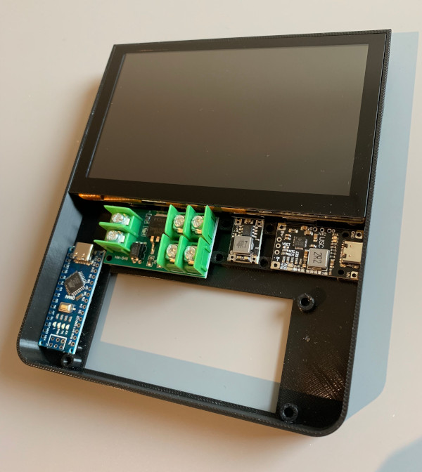
The massive FET board quickly catches the eye. The board in the picture is just to showcase how out-of-place it really is. I swapped it with a smaller one before continueing.
Swapping the FET board was harder than I thought. There are many pre-built modules available, but most of them are built with N-FETs and not P-FETs. The N-FET boards are cheaper and easier to build, and result in an electronic switch that switches the GND wire. I would later find out that I need a P-FET, because I need a common ground connected at all times for the Arduino logic and the Pi logic to work together (for I2C communication).
In the end, I couldn’t find a small enough FET board, so I started reverse-engineering the existing one in my very first KiCad project:
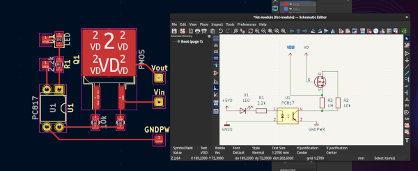
and then rebuilding it on an experiment board:
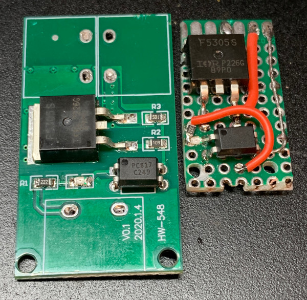
I might make a custom PCB in the future. That way, I can add some connectors for various components, making the project easier to assemble.
Before the custom FET board, I was able to get most of the basic components working before adding the Pi to the mix.
I would quickly find out that I didn’t have the correct wire thickness for the main power. I was using 20 AWG, which I use
for drones that draw way more power. I would later replace them with 24 AWG wires.
When I was working on the Arduino firmware, I had a problem: every time I would upload a new firmware, the Arduino would restart. This would make the electronic switch go off, and thus restart the Pi. To overcome this, I would wire a second Arduino to I2C, isntead of using the one in the device. At a later stage, I also added a JST-SH connector to be able to easily disconnect the Arduino inside the device.
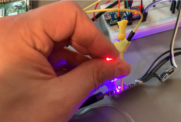
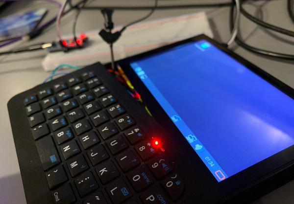
Charging status LEDs would be a nice touch. But adding 1 or 2 LEDs to the case would require a relatively considerable effort. And then it hit me: I could use fiber optics! Fishing wire (or flexible bracelet wire) can guide the light from the existing LEDs on the BMS to the edge of the case. All I would have to do is glue the wire in place. An overnight shipping and a quick experiment later, the theory was proven:
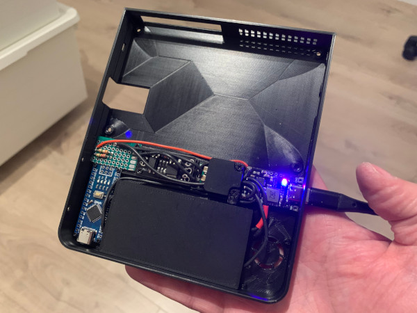
After a lot of iterations, the hardware was finally finished:
At this point, a custom I2C device implementation was enabling the Pi and the Arduino to talk to eachother. The Pi could ask the Arduino about the charging status or the battery voltage, and the Arduino would report it back. I started investigating how to integrate it into a Linux desktop, so I read about dbus and upower. At first, the intention was to write a custom kernel driver, but then it hit me: What if I change my Arduino firmware so that it acts like an already supported Linux device? I did some research and settled on the LTC294x “Battery Fuel Gauges” implementation. It was one of the very few power-related Linux kernel drivers that were avaible in Raspberry Pi OS. The Arduino now acts like such a device, so it is fully supported in Linux.
I was stoked when I saw the battery icon appear for the first time:
Various learnings
Here’s a quick summarization of some noteworthy learnings that aren’t covered above:
As mentioned before, airflow was important. I had to cool the BMS board and also the Pi. Some holes for airflow would be insufficient. I ended up roughly aligning my components in the direct airflow of the fan. This ended up also as a bit of a constraint on the rest of the electronics design, as I wouldn’t be able to easily move the BMS board anymore.
Less fasteners(/parts) is better: The best fastener is the one you don’t need. If you create a groove and latch mechanism to save yourself some parts, it might be worth it! The cost for me was added complexity in the design.
Designing for … 3D printers? Or CNC milling? The plan was to initially make a 3D printed case and then later attempt an aluminum CNC-milled case. Designing for 3D printers is very different. It would require changes to make the cases millable on a 3 axis mill.
Electronics placement is difficult: Next to the airflow considerations, you also have to consider the amount of wiring needed to connect all the parts. I also wanted to make the build as small as I could. Finding the best trade-off is not an easy task. Then there is theory versus usability: Your SD card might fit in the slot, but is it easy to pull it out? Can you grip it with your nail?
3D printing - Chamfer is life: I used chamfers on overhangs as to not require support when 3D printing them. I also used chamfers on certain edges near case openings (e.g. ethernet and GPIO connectors), to slide objects into the case more easily.
3D printing - Manual painted-on supports: These are very handy if you have lots of overhangs, but only some of them need support. (used with SuperSlicer/PrusaSlicer)
3D printing - Parts can flex: If you make a battery tray, the pressure of the battery inside the case might budge it outward. This can result in your battery tray not being placeable when batteries are in it. More importantly: you should measure the flex and see if it’s bending outwards too much, because you don’t want a critical failure with lithium cells.
Use SSH to the fullest: I increased my dev cycle by using remote commands. I could execute my local Python remotely with ssh me@cyberdeck 'python' < powermanager.py
Raspberry Pi 4 has more than two I2C buses: When you fry your CM4 I2C bus, you can use other GPIO pins to create extra I2C ports.
Naming your project matters: While “Decktility” is probably not the best name out there, it is a good name because it’s easy to remember, and it’s a unique name so an online search will easily turn up the correct results. You can use ChatGPT to help you find a good name. (Decktility refers to ductility/utility, where ductility is a wink towards the welder part in my online persona)
Closing words
If you want more details, check out the Decktility GitHub repository.